dienelectrics@gmail.com
 0909186879 dienelectrics@gmail.com
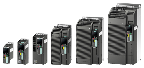

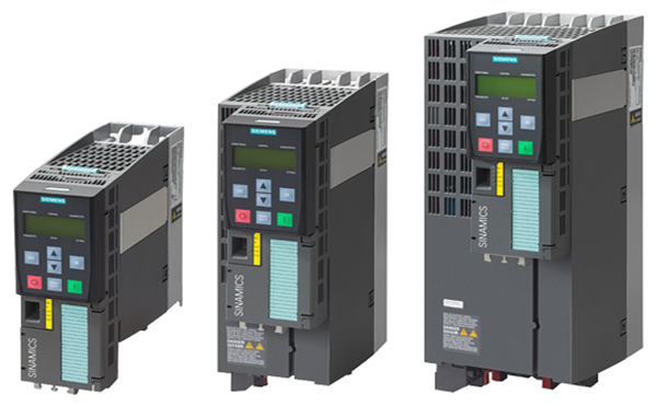
PM240‑2 Power Modules, degree of protection IP20, Push Through variant, frame sizes FSA to FSC (with Control Unit and Operator Panel)
Power Modules PM240-2
PM240-2 Power Modules have a braking chopper (four-quadrant applications) and are suitable for a large number of applications in general machinery contruction.
Power Modules PM240-2 will be available for the following voltage and power ranges:
1 AC / 3 AC 200 V ... 240 V 0.55 kW ... 4.0 kW
3 AC 200 V ... 240 V 5.5 kW ... 7.5 kW
3 AC 380 V ... 480 V 0.55 kW ... 250 kW
3 AC 500 V ... 690 V 11 kW ... 132 kW
The new PM240‑2 Power Modules are based on a new hardware platform. This permits an increase in power density as well as the application of innovative cooling concepts (Push Through technology) with especially high requirements in terms of control cabinet cooling.
Furthermore, the PM240-2 Power Module is also suitable for use in safety-oriented applications. In conjunction with a fail-safe Control Unit, the drive can be transformed into a Safety Integrated Drive (see section Control Units).
The PM240‑2 Power Modules frame sizes FSA to FSC are available both with and without an integrated line filter class A of compact design for 200 V and 400 V line voltages.
The PM240-2 Power Modules with integrated line filter class A are suitable for connection to TN supply systems. Power Modules without integrated line filter can be connected to grounded TN/TT systems and non-grounded IT systems.
The permissible cable lengths between inverter and motor are limited (for max. permissible cable lengths, see Integration). Longer cables can be used if output reactors are connected (see section Load-side power components).
Push Through variant
The Push Through variant allows the cooling fins of the Power Module to be pushed through the rear panel of the control cabinet. Push Through variants should be used in applications where the amount of power loss generated inside the control cabinet itself must be minimized.
Shield plates and shield connection kits are available. These can be used in the wiring installation for the Control Units and Power Modules to ensure that it complies with EMC guidelines.
For more information, see Shield connection kits and shield plates for Control Units and Power Modules in section Supplementary system components.

PM240 Power Modules frame size FSGX optionally have a braking chopper (four-quadrant applications) and are suitable for a large number of applications in general machinery construction.
For Power Modules frame size FSGX, an optional plug-in Braking Module can be ordered (see section DC link components).
The permissible cable lengths between inverter and motor are limited (for max. permissible cable lengths, see Integration). Longer cables can be used if output reactors are connected (see section Load-side power components).
Line reactors are available to minimize line harmonics as well as voltage and current peaks (see section Line-side power components).
The PM240 Power Module is suitable for safety-oriented applications. In conjunction with a fail-safe Control Unit, the drive can be transformed into a Safety Integrated Drive (see section Control Units).
PM240 Power Modules, frame size FSGX (i.e. 160 kW/250 hp and higher) are approved only for the Basic Safety functions (STO, SS1, and SBC).
Power Modules without integrated line filter can be connected to grounded TN/TT systems and non-grounded IT systems.
Note:
Shield plates and shield connection kits are available. These can be used in the wiring installation for the Control Units and Power Modules to ensure that it complies with EMC guidelines.
For more information, see Shield connection kits and shield plates for Control Units and Power Modules in section Supplementary system components.
Power Modules PM250
PM250 Power Modules are suitable for the same applications as the PM240 Power Modules. Any braking energy is directly fed back into the line supply (four quadrant applications - a braking chopper is not required).
.JPG)
PM 250 Power Modules, frame sizes FSC to FSF
Power Modules PM250 will be available for the following voltage and power ranges:
3 AC 380 V ... 480 V 7.5 kW ... 90 kW

PM250 Power Modules, frame sizes FSC to FSF
PM250 Power Modules are suitable for a large number of applications in general mechanical engineering. Any braking energy is directly fed back into the line supply (four-quadrant applications – a braking chopper is not required).
The PM250 Power Module features an absolutely unique technology – Efficient Infeed Technology. This feature provides the ability to feed energy back into the supply system in the generator mode (electronic braking) so that the energy is not wasted in a braking resistor. This saves space in the control cabinet. The time-consuming process of dimensioning the braking resistor and the expense of the extra wiring are eliminated. Furthermore, heat losses in the control cabinet are reduced.
Additional information is provided in chapter Highlights, section Efficient Infeed Technology.
Further, the innovative circuit design reduces the line harmonics. There is no need to use an optional line reactor at the supply infeed. This saves space and costs for engineering and procurement.
The permissible cable lengths between inverter and motor are limited (for max. permissible cable lengths, see Integration). Longer cables can be used if output reactors are connected (see section Load-side power components).
Frame sizes FSD to FSF of the PM250 Power Modules are available both with as well as without integrated line filter class A.
For frame size FSC of the PM250 Power Module with an integrated line filter class A, an additional base filter of class B is available for achieving class B (see section "Line-side power components").
The PM250 Power Module is also designed for safety-oriented applications. In conjunction with a fail-safe Control Unit, the drive can be transformed into a Safety Integrated Drive (see section Control Units).
The PM250 Power Modules with integrated line filter class A are suitable for connection to TN supply systems. Power Modules without integrated line filter can be connected to grounded TN/TT systems and non-grounded IT systems.
Note:
Shield plates and shield connection kits are available. These can be used in the wiring installation for the Control Units and Power Modules to ensure that it complies with EMC guidelines.
For more information, see Shield connection kits and shield plates for Control Units and Power Modules in section Supplementary system components.
All Power Modules have the following connections and interfaces:
- PM‑IF interface to connect the Power Module to the Control Unit. The Power Module also supplies power to the Control Unit using an integrated power supply
Connection diagram for PM240‑2 Power Modules, frame sizes FSA to FSC, with or without integrated line filter

Connection diagram for PM240‑2 Power Modules, frame sizes FSD to FSF, with or without integrated line filter

Connection diagram for PM240 Power Modules, frame size FSGX

Connection diagram for PM250 Power Module with or without integrated line filter
The following line-side power components, DC link components and load-side power components are optionally available in the appropriate frames sizes for the Power Modules:
|
|
Frame size |
||||||
|---|---|---|---|---|---|---|---|
|
|
FSA |
FSB |
FSC |
FSD |
FSE |
FSF |
FSGX |
|
PM240-2 Power Module with integrated braking chopper |
|||||||
|
Available frame sizes |
|
|
|
|
|
|
|
|
✓ |
✓ |
✓ |
✓ 3) |
✓ 3) |
✓ 3) |
– |
|
✓ |
✓ |
✓ |
✓ |
✓ |
✓ |
– |
|
– |
– |
– |
✓ |
✓ |
✓ |
– |
|
Line-side power components |
|||||||
|
Line filter class A |
I |
I |
I |
I 3) |
I 3) |
I 3) |
– |
|
Line filter class B (only for 400 V versions) |
U 1) |
U 1) |
U 1) |
– |
– |
– |
– |
|
Line reactors (only for 3 AC versions) |
S |
S |
S |
I |
I |
I |
– |
|
DC link components |
|||||||
|
Braking resistor |
S |
S |
S |
S |
S |
S |
– |
|
Braking Module |
– |
– |
– |
– |
– |
– |
– |
|
Load-side power components |
|||||||
|
Output reactor |
S |
S |
S |
– |
– |
– |
– |
|
Sine-wave filter |
– |
– |
– |
– |
– |
– |
– |
|
PM240 Power Module without integrated braking module |
|||||||
|
Available frame sizes |
– |
– |
– |
– |
– |
– |
✓ |
|
Line-side power components |
|||||||
|
Line filter class A |
– |
– |
– |
– |
– |
– |
S 4) |
|
Line filter class B |
– |
– |
– |
– |
– |
– |
– |
|
Line reactor |
– |
– |
– |
– |
– |
– |
S |
|
DC link components |
|||||||
|
Braking resistor |
– |
– |
– |
– |
– |
– |
S |
|
Braking Module |
– |
– |
– |
– |
– |
– |
I (option) |
|
Load-side power components |
|||||||
|
Output reactor |
– |
– |
– |
– |
– |
– |
S |
|
Sine-wave filter |
– |
– |
– |
– |
– |
– |
S |
|
PM250 Power Module with line-commutated energy recovery |
|||||||
|
Available frame sizes |
– |
– |
✓ |
✓ |
✓ |
✓ |
– |
|
Line-side power components |
|||||||
|
Line filter class A |
– |
– |
I |
F |
F |
F |
– |
|
Line filter class B |
– |
– |
U |
– |
– |
– |
– |
|
Line reactor 2) |
– |
– |
– 2) |
– 2) |
– 2) |
– 2) |
– |
|
DC link components |
|||||||
|
Braking resistor 5) |
– |
– |
– 5) |
– 5) |
– 5) |
– 5) |
– |
|
Load-side power components |
|||||||
|
Output reactor |
– |
– |
U |
S |
S |
S |
– |
|
Sine-wave filter |
– |
– |
U |
S |
S |
S |
– |
U = Base component
S = Lateral mounting
I = Integrated
F = Power Modules available with and without integrated class A filter
– = Not possible
1) Lateral mounting is the only possible option for Push Through variants.
2) A line reactor is not required and must not be used in conjunction with a PM250 Power Module.
3) PM240‑2 200 V versions, frame sizes FSD to FSF are only available without integrated line filter.
4) PM240 Power Modules, frame size FSGX, are available only without an integrated filter class A. An optional line filter class A for lateral mounting is available instead.
5) A PM250 Power Module is capable of line-commutated energy feedback. A braking resistor cannot be connected and is not necessary.
General design information

Inverter comprising a Power Module (PM), a Control Unit (CU), and base components (side view)
- If at all possible, the line filter should be mounted directly below the inverter 1).
- With lateral mounting, the line-side components have to be mounted on the left side of the inverter, and the load-side
components on the right side.
- Braking resistors have to be mounted directly on the control cabinet wall due to heating issues.
Recommended installation combinations of the inverter and optional power and DC link components
|
Power Module |
Base |
Lateral mounting |
|
|---|---|---|---|
|
Frame size |
|
To the left of the inverter |
To the right of the inverter |
|
FSA and FSB |
Line filter |
Line reactor |
Output reactor and/or |
|
FSC |
Line filter 1) |
Line reactor |
Output reactor and/or |
|
FSD and FSE |
– |
Line filter |
Output reactor or |
|
FSF |
– |
Line filters |
Output reactor or |
|
FSGX |
– |
Line filter and/or |
Output reactor or |
1) With the PM250 Power Module, frame size FSC, the output reactor and sine-wave filter cannot be installed as base components. The output reactor or sine-wave filter should be mounted under the line filter.
Maximum permissible cable lengths from the motor to the inverter when using output reactors or filters depending on the voltage range and the Power Module being used
The following load-side power components in the appropriate frame sizes are optionally available for the Power Modules and result in the following maximum cable lengths:
|
|
Maximum permissible motor cable lengths (shielded/unshielded) in m (ft) |
||||||
|---|---|---|---|---|---|---|---|
|
Frame size |
FSA |
FSB |
FSC |
FSD |
FSE |
FSF |
FSGX |
|
PM240-2 Power Module with integrated braking chopper |
|||||||
|
Available frame sizes |
|
|
|
|
|
|
|
|
✓ |
✓ |
✓ |
✓ |
✓ |
✓ |
– |
|
✓ |
✓ |
✓ |
✓ |
✓ |
✓ |
– |
|
– |
– |
– |
✓ |
✓ |
✓ |
– |
|
With optional output reactor |
|
|
|
|
|
|
|
|
150/225 (492/738) |
150/225 (492/738) |
150/225 (492/738) |
– |
– |
– |
– |
|
150/225 (492/738) |
150/225 (492/738) |
150/225 (492/738) |
– |
– |
– |
– |
|
100/150 (328/492) |
100/150 (328/492) |
100/150 (328/492) |
– |
– |
– |
– |
|
With integrated line filter class A (EMC category C2) |
|
|
|
|
|
|
|
|
50/- (164/–) |
50/- (164/-) |
50/- (164/-) |
– |
– |
– |
– |
|
50/- (164/-) |
100/– (328/-)2) |
150/– (492/-) 2) |
150/- (492/-) |
150/- (492/-) |
150/- (492/-) |
– |
|
– |
– |
– |
100/- (328/-) |
100/- (328/-) |
150/- (492/-) (category C3) |
– |
|
With optional external line filter class B (for compliance with EMC category C1 1), with unfiltered Power Module, maintains the limit values acc. to EN 61800‑3) |
|
|
|
|
|
|
|
|
50/- (164/-) |
50/- (164/-) |
50/- (164/-) |
– |
– |
– |
– |
|
With optional external line filter class B and output reactor (for compliance with EMC category C2 1), with unfiltered Power Module, maintains the limit values acc. to EN 61800‑3) |
|
|
|
|
|
|
|
|
150/- (492/-) |
150/- (492/-) |
150/- (492/-) |
– |
– |
– |
– |
|
100/- (328/-) |
100/- (328/-) |
100/- (328/-) |
– |
– |
– |
– |
|
PM240 Power Module without integrated braking module |
|||||||
|
Available frame sizes |
– |
– |
– |
– |
– |
– |
✓ |
|
With optional output reactor |
|
|
|
|
|
|
|
|
– |
– |
– |
– |
– |
– |
300/450 (984/1476) |
|
With optional sine-wave filter |
|
|
|
|
|
|
|
|
– |
– |
– |
– |
– |
– |
300/450 (984/1476) |
|
PM250 Power Module with line-commutated energy recovery |
|||||||
|
Available frame sizes |
– |
– |
✓ |
✓ |
✓ |
✓ |
– |
|
With optional output reactor |
|
|
|
|
|
|
|
|
– |
– |
150/225 (492/738) |
200/300 (656/984) |
200/300 (656/984) |
200/300 (656/984) |
– |
|
– |
– |
100/150 (328/492) |
200/300 (656/984) |
200/300 (656/984) |
200/300 (656/984) |
– |
|
With optional sine-wave filter |
|
|
|
|
|
|
|
|
– |
– |
200/300 (656/984) |
200/300 (656/984) |
200/300 (656/984) |
200/300 (656/984) |
– |
1) Further information is available on the Internet at http://www.siemens.com/sinamics-g120/documentation
2) The values apply with low-capacitance CY cables - the max. permissible motor cable length is 50 m (164 ft) (shielded) as standard.

|
Frame size |
Dimensions in mm (inches) |
Drilling dimensions in mm (inches) |
Cooling clearance 2) in mm (inches) |
Mounting |
||||||
|---|---|---|---|---|---|---|---|---|---|---|
|
|
a |
b |
c |
d |
e |
f |
top |
bottom |
front |
With bolts |
|
PM240-2 Power Modules, standard variant, with/without integrated line filter class A |
||||||||||
|
FSA |
73 |
196 |
165 |
62.3 |
186 |
6 |
80 |
100 |
0 |
3 × M4 |
|
FSB |
100 |
291 |
165 |
80 |
281 |
6 |
80 |
100 |
0 |
4 × M4 |
|
FSC |
140 |
355 |
165 |
120 |
343 |
6 |
80 |
100 |
0 |
4 × M5 |
|
FSD |
200 |
472 |
237 |
170 |
430 |
7 |
300 |
350 |
100 |
4 × M5 |
|
FSE |
275 |
551 |
237 |
230 |
509 |
8.5 |
300 |
350 |
100 |
4 x M6 |
|
FSF |
305 |
709 |
357 |
270 |
680 |
13 |
300 |
350 |
100 |
4 × M8 |
(Nguyễn Thảo Trường - http://DienElectric.Com theo Siemens)